


1. The mechanical tests are static bending, compression parallel to grain, impact bending toughness, compression perpendicular to grain, hardness, shear parallel to grain, cleavage, tension parallel to grain, tension-perpendicular to-grain, and nail-withdrawal tests. These tests may be made on both green and air-dry material as specified in these test methods. In addition, test methods for evaluating such physical properties as specific gravity, shrinkage in volume, radial shrinkage, and tangential shrinkage are presented.
Static Bending
1. Size of Specimens
The static bending tests shall be made on 2 by 2 by 30 in. (50 by 50 by 760 mm) primary method specimens or 1 by 1 by 16 in. (25 by 25 by 410 mm) secondary method specimens. The actual height and width at the center and the length shall be measured.
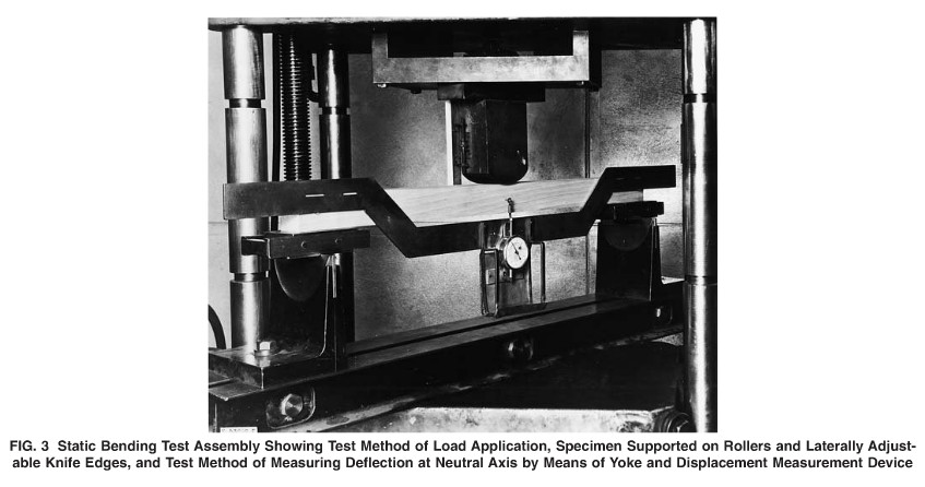
2. Loading Span and Supports
Use center loading and a span length of 28 in. (710 mm) for the primary method and 14 in. (360 mm) for the secondary method. These spans were established in order to maintain a minimum span-to-depth ratio of 14. Both supporting knife edges shall be provided with bearing plates and rollers ofsuch thickness that the distance from the point of support to the central plane is not greater than the depth of the specimen. The knife edges shall be adjustable laterally to permit adjustment for slight twist in the specimen.
3. Bearing Block
A bearing block of the form and size of that shown in Fig. 4 shall be used for applying the load for primary method specimens. A block having a radius of 1 1/2 in (38 mm) for a chord length of not less than 2 in. (50 mm) shal be used for secondary method specimens.
4. Placement of Growth Rings
The specimen shall be placed so that the load will be applied through the bearing block to the tangential surface nearest the pith.
5. Speed of Testing
The load shall be applied continuously throughout the test at a rate of motion of the movable crosshead of 0.10 in. (2.5 mm)/min, for primary method specimens, and at a rate of 0.05 in. (1.3 mm)/min for secondary method specimens.
6. Load-Deflection Curves:
6.1 At a minimum, the load-deflection curves shall be recorded and the test continued up to the maximum load for all static bending tests. If required for the purposes of the study. it shall be permitted to continue both loading and the load deflection measurement beyond the maximum load.
7. Description of Static Bending Failures
Static bending (flexural) failures shall be classified in accordance with the appearance of the fractured surface and the manner in which the failure develops. The fractured surfaces may be roughly divided into "brash" and "fibrous", the term "brash" indicating abrupt failure and "fibrous" indicating a fracture showing splinters.
8. Weight and Moisture Content
The specimen shall be weighed immediately before test, and after the test a moisture section approximately 1in. (25 mm) in length shall be cut from the specimen near the point of failure.